SPRING EMC BREAK IN FLORIDA

Posted March 29, 2017 by Henry Ott
Categories: EMC Seminars, EMC Training

Warm up to EMC. On May 16-18, 2017, in partnership with IN Compliance magazine I will be presenting a three-day public  Electromagnetic Compatibility Engineering Seminar in Cocoa Beach, Florida (Orlando/Melbourne area), including  one-day (5/17/17) of concurrent EMC Exhibits. Includes, by popular request, a session on Pre-Compliance EMC Measurements.

This three-day intensive EMC seminar and exhibit covers the practical aspects of noise and interference control in electronic systems, and provides a working knowledge of EMC principles. Emphasis is on the cost-effective design of analog and digital systems. Commercial, industrial, medical, military, and aerospace aspects of EMC are emphasized. The amount and complexity of mathematics is kept to a minimum, and concepts are illustrated with examples of actual case histories.

Participants will obtain the knowledge necessary to design electronic equipment that is compatible with the electromagnetic environment, and is in compliance with national and international EMC regulations.

Topics covered include:

  • Cabling
  • Grounding Principles
  • Digital Layout and Grounding
  • High-Speed Digital Decoupling
  • Radiated Emission Control, both Common-Mode and Differential-Mode
  • Pre-Compliance EMC Measurements
  • Common-Mode Filters
  • Digital Transmission Lines
  • RF and Transient Immunity
  • Conducted Emission Control, both Common-Mode and Differential-Mode
  • Shielding Principles and Applications
  • Mixed Signal PCB Grounding and Layout

This seminar is directed towards electrical engineers, however, mechanical engineers, reliability and regulatory compliance engineers, technical managers, EMC test personnel, technicians, and others who need a working knowledge of electromagnetic compatibility principles will also benefit from attending.

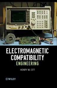
In addition to the class notes, participants will receive a copy of both my latest 872 page award-winning* book, Electromagnetic Compatibility Engineering, published by John Wiley in 2009, and the Electromagnetic Compatibility EMC Pocket Guide by Ken Wyatt and Randy Jost, published by Scitech in 2013.

* Association of American Publishers “2009 PROSE Award” in the field of Engineering & Technology.

On Wednesday, May 17, 2017, we will welcome a small group of EMC companies who will exhibit their products and services. During breakfast, morning and afternoon breaks, and an extended lunch, course attendees will have time to visit exhibitors’ displays and connect with some of the industry’s top suppliers, including test laboratories, test equipment companies, and EMC component manufacturers. After Wednesday’s technical session, we will all get together at a reception sponsored by the exhibitors for some food, drink, and good EMC comradery.

Comments from a few previous seminar attendees:

  • “I had high expectations for this course, high enough to justify travel from the opposite side of the planet. Henry exceeded them all!”
  • “I learned a lot of what I thought I knew was wrong, and when it was right I learned why it was right.”
  • “EMC demystified! It’s not black magic as many claim.”
  • “Probably the most useful technical seminar I have ever attended. Should have learned this 20 years ago.”
  • “This is the best practical course available.”
  • “An excellent seminar presented by a pragmatic, knowledgeable, entertaining teacher.”
  • “Excellent course! Presented in a very understandable way, even for a mechanical engineer.”

Registration is limited – so sign up early to guarantee your place. Sign up by April 7, 2017 and take advantage of a $200 early registration discount. Don’t miss this opportunity, click here for more information.

Antenna Modeling Software for the MAC

Posted March 23, 2015 by Henry Ott
Categories: Antennas

Tags:

I like using MAC computers because of the inherent stability of the underlying UNIX operating system, and the immunity to most viruses. One disadvantage, however, is that not all types of programs are written for the MAC. I occasionally have need for an antenna modeling program. On my windows PC, I used EZNEC (http://www.eznec.com) which costs about $100.

I have always wished to have a similar program for the MAC. I have now found an even better program than EZNEC, that is written specifically for the MAC. The program is “cocoaNEC” (http://www.w7ay.net/site/Applications/cocoaNEC/) written by Kok Chen a retired Apple software engineer. The program will run on OS X 10.6 or later, I have been running mine on the latest MAC operating system OS X 10.10, Yosemite, with no problems. This elegant and fast running program is written in OS X’s native programming language. This program takes advantage of all the cores of a modern Intel processor, therefore, it runs fast. The best part, however, is that the program is free.

The downloaded program includes a reference manual and tutorial. Example antenna files can also be downloaded from Kok’s webpage. “cocoaNEC” uses the NEC-2  computational engine. NEC (Numerical Electromagnics Code) was developed by Lawrence Livermore Laboratories in 1981 to simulate the electromagnetic response of antennas and other metal structures.

The antenna characteristics can be input in either one of two ways, via a tabular spreadsheet interface or a special NC programing language interface.  The spreadsheet approach is simpler, however, the NC programing interface is more powerful. The antenna’s input information consists of its geometry (for a conductor, the x, y, z coordinates of its endpoints), its excitation, and type of ground (if any).

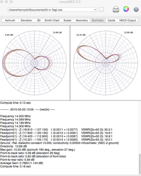
The summary output for a three-element Yagi antenna located 10-meters above the ground is shown below.

Yagi-3

The different color lines represent different frequencies. The antenna can be modeled in free space or above a conducting ground, and the ground conductivity can be varied.

Other outputs consist of a 3-dimensional radiation pattern, driving point impedance and VSWR, as well as a physical plot of the antenna’s geometrical structure. Currents in the various conductors making up the antenna elements can also be plotted, as well as a complete tabulation of the NEC  engine output.

If you are a MAC user and have the need to do some antenna modeling, give cocoaNEC a try, I think that you will like it.

Ferrite Cores For Low-Frequency EMI Cable Suppression

Posted March 7, 2014 by Henry Ott
Categories: EMC Components, Troubleshooting

Tags:

Ferrite cores (chokes) provide an inexpensive, and effective, way of coupling high-frequency resistance into a cable in order to reduce the  common-mode current, and hence the radiation (or pickup) from the cable. They are commonly used  on mouse, keyboard, video, and other peripheral cables connected to personal computers, as well as on power supply cables when a device is powered from an external transformer (wall-wart) or power supply. The ferrite core acts as a one-turn common-mode choke, and can be effective in reducing the conducted and/or radiated emission from the cable, as well as suppressing high-frequency pick-up in the cable. Basically ferrites can be thought of as high-frequency resistors, with little or no impedance at low-frequencies or dc. Ferrite cores are most effective in providing attenuation of  unwanted noise signals above 10 MHz. The figure below shows a ferrite choke on a USB cable.

ch05fg32

For low-frequency cable emission problems, typically below 10 MHz, ferrite chokes have not been very useful, since their impedance is too low, at these frequencies, to be effective. I have always wished  for a similar, simple low-frequency solution to cable emission/susceptibility problems. My wish finally has been granted.

Recently Fair-Rite Products Corp. introduced a new low-frequency, Type 75, ferrite material optimized for EMI suppression in the 200 kHz to 30 MHz frequency range. This material has an impedance peak in the 1 to 2 MHz range. Information on the new Type 75 ferrite cores is included in Fair-Rite’s  17th edition catalog.

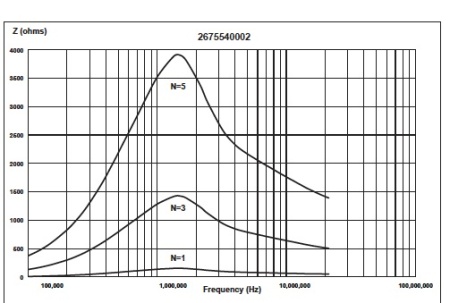
For example,  part number 2675540002 (9/16″ OD,  1/4″ ID , and 1-1/8″ long core) has a peak impedance of  160 Ω at about 1.6 MHz as shown below.

2675540002-1

Type 75 ferrite cores can be especially useful in reducing emission problems in the 500 kHz to 10 MHz frequency range, across which the impedance of the above ferrite is greater than 80 Ω..

The impedance of  ferrite cores can be further increased by using multiple turns. However, this also increases the inter-winding capacitance and degrades the high-frequency performance of the choke. Since the Type 75 material is intended for low-frequency use, this increase in capacitance is less of an issue, and two to five turns can be used with very little, if any, detrimental effect. The same 2675540002 core discussed above has an impedance of 1,400 Ω at 1.3 MHz when three turns are used, and an impedance of almost 4,000 Ω when five turns are used, see below. A three turn choke using this core will have an impedance greater than 500 Ω from 300 kHz to 20 MHz.

2675540002-2

Even at 150 kHz, the low-end of the FCC/CISPR conducted emission measurement range, the three turn configuration has an impedance of approximately 250 Ω, and the five turn configuration has an impedance of approximately 700 Ω. Therefore, by using multiple turns high impedances can now be obtained at these low-frequencies.

Both smaller and larger cores are available from Fair-Rite. Type 75 cores ranging from 3/8″ to 1-1/4″ OD (7/32″ to 3/4″ ID) are listed in the Fair-Rite catalog. At present only solid cores are available, but snap-on split cores should also be available later this year. Snap-on cores are convenient for troubleshooting, and can be easily applied as an after-the-fact fix to cables. Since the manganese-zinc (MnZn) Type 75 cores are slightly conductive (resistivity, ρ = 3×10^2 Ω-cm), care should be taken that they do not touch any live electrical terminals.

For more information  on this new low-frequency ferrite material, check out Fair-Rite’s Low-Frequency Suppression Flyer, a pdf copy of which is available  at:

Click to access LowFreqSuppression.pdf

Give the new Fair-Rite Type 75 material a try for your low-frequency emission/susceptibility cable problems. You might be pleasantly suppressed with the results.

Workbench EMC Measurements

Posted July 6, 2012 by Henry Ott
Categories: Test Equipment, Troubleshooting

Tags:

I have just posted a new article on “Workbench EMC Measurements” to the Tech Tips section of my webpage (www.hottconsultants.com). Workbench EMC measurements are simple, inexpensive, precompliance tests that a product designer can perform, in his/her own laboratory, early in the development phase of a product in order to obtain an indication of the EMC performance of the product.

The link to the article is:

www.hottconsultants.com/techtips/Workbench_EMC_Measurements.pdf

Digital Logic Return Current Flow

Posted March 3, 2012 by Henry Ott
Categories: Theory

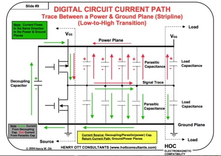
The lowest impedance (inductance) signal return path for high-frequency current is in a plane directly adjacent to the signal trace. What one wants is the smallest signal current loop area possible. In order to evaluate a PCB layout/stackup and determine if this objective is achieved or not, one must first know exactly how the actual return current flows on the PCB.

Many designers/engineers, however, are confused about how and where digital logic return currents flow, and what is the source of the digital logic current. In my EMC Seminars, I receive many questions relating to this subject, typical question are:

  1. Is it better to have a digital logic trace adjacent to a ground plane, or adjacent to a power plane?
  2. What about a trace between a power and ground plane?
  3. Would it be better to have the trace between two ground planes, or possibly two power planes?

To answer these questions we must know two things:

  • What is the source of the current?
  • What is the path taken by the current in returning to the source?

First let me state that the logic gate is not the source of the current, the logic gate only acts as a switch. Only the transient (switching) current is important, and the transient current is not dependent on the existence of the load at the end of the line. The source of the current is either:

  • The driver’s decoupling capacitor, or
  • The parasitic signal trace to ground/power plane capacitance in parallel with the load capacitance

The return current path is a function of:

  • The trace configuration, microstrip or stripline
  • The adjacent plane or planes (power and/or ground), and
  • The logic transition (low-to-high, or high-to-low)

There are ten possible combinations of the above.

To answer the question “what is the return current path?”, I created the following Power Point presentation. Click here to view the presentation.

Power Point Presentation - Digital Logic Current Flow

From the ten examples presented in the above presentation, it can be concluded that it makes no difference whatsoever if the adjacent plane, or planes, are ground or power. In all cases the current returns directly to the source through a small loop. In none of the cases does the current have to go out of its way, or flow through a large loop, in order to return to the source.

Therefore, the answer to the original three questions is that it does not matter if the return path is the ground plane or the power plane, all configurations are equally acceptable.

We can, however, conclude that stripline is always better than microstrip since two current loops exist, and in one loop the current flow is clockwise and in the other loop the current flow is counterclockwise. Therefore, the radiation from the two loops tend to cancel each other.

With respect to the question of what is the source of the current, this is summarized in the table on slide 13 of the presentation.

Note: That the power plane discussed in the above presentation is the same voltage as that supplying the driver. The case of referencing a power plane not the same as the driver voltage is a different subject–possibly the topic of a future blog.

Reference: Ott, H. W., “Electromagnetic Compatibility Engineering,” Section 10.7, Digital Logic Current Flow, John Wiley & Sons, 2009.

Three Book EMC/Signal Integrity Library

Posted January 29, 2012 by Henry Ott
Categories: Book Rviews, EMC Training, Theory

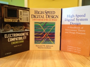
Would you like to have a mini-library on the subject of EMC and Signal Integrity that covers the frequency range from DC to light. The following three books, all highly recommended, will accomplish that. All the books are very readable, with a minimum of mathematics, and as a bonus there is very little overlap between the material contained in each of the books. I refer to all three of these books regularly.

Three Book Mini EMC Library

Electromagnetic Compatibility Engineering, by Henry W. Ott, published by John Wiley & Sons in 2009 has won the PROSE Award from the Association of American Publishers for the best book published in 2009 in the category of Engineering and Technology. It is the most comprehensive book on the subject and is the first EMC book that you should read. In addition to the core subjects of cabling, grounding, balancing, filtering, and shielding that made my previous book, Noise Reduction Techniques in Electronic Systems, an international success (translated into six other languages), this new book includes additional coverage of equipment and systems grounding, switching power supplies and variable speed motor drives, digital circuit power distribution and decoupling, PCB layout and stackup, mixed-signal PCB layout, rf and transient immunity, power line disturbances, and simple pre-compliance EMC measurements. Written in an easy to read and understandable style, it’s full of real-life practical examples. This book contains eighteen chapters, six appendices, and 872 pages.

High-Speed Digital Design, by Howard Johnson and Marty Graham, published by Prentice Hall in 1993 picks up where Electromagnetic Compatibility Engineering leaves off, with respect to high-speed digital circuits. Despite its title, this is more an EMC book than a classical digital design book. Its subtitle, “A Handbook of Black Magic,” gives away its true nature. Besides containing much practical information on the EMC aspects of high-speed digital design, the book also contains useful information on various measurement techniques that can be used to measure such things as power-ground plane impedance, metastable states, etc. Subjects include transmission lines, terminations, vias, clock distribution, clock oscillators, ribbon cables and connectors, layer stackup, and power distribution. This book is considered by many as a “crossover book” covering both EMC and signal integrity. Everything in this book is easy to read and practical. A “must have” book if you are designing high-speed digital circuits! This book contains twelve chapters, three appendices, and 447 pages.

High-Speed Digital System Design, by Hall, Hall, and McCall, published by John Wiley and Sons in 2000 continues where the Johnson and Graham book ends. This is a signal integrity book! It is very well written with a good balance between theory and practical applications. The first sentence of the book sets the tone of the book; it reads, The speed of light is just too slow. Subjects include transmission line considerations, crosstalk, IC package and pin-out considerations, power delivery and decoupling, non-ideal current return paths, simultaneous switching noise, timing and skew considerations, and radiation. The book also includes a chapter on design methodologies useful in the design of high-speed systems with a large number of variables. As does the Johnson and Graham book, this book  contains a chapter on high-speed measurement techniques. The information contained in this book is useful at both the IC and PCB level. This book contains eleven chapters, six appendices, and 347 pages.

******

Want to expand your library by adding two additional books that fall on either end of the spectrum from the above three core books? Then consider the following two books:

Two Additional EMC Books

EDN Designer’s Guide to Electromagnetic Compatibility, Second Edition, by Bill Kimmel and Daryl Gerke, 2000 (originally published by EDN magazine in 1994), is a practical nuts and bolts approach to EMI, written for the non-EMI expert. One hundred pages of down-to-earth practical advice on EMC, without any equations or mathematics, by two authors who work regularly in the EMC trenches. The paperback book is available on the authors’ web site.

Introduction to Electromagnetic Compatibility, Second Edition, by Clayton Paul, published by John Wiley and Sons in 2006 is more theoretical than any of the other books, as it was intended to be used for a university course in EMC. A good book to get more detail on the theory behind EMC. Lots of useful information, especially the chapter on crosstalk, a subject that Dr. Paul is considered to be a leading expert. This book contains eleven chapters, four appendices, and 1016 pages.

So there you have it, three, (or possibly five) books that cover 90% of what you need to know about Electromagnetic Compatibility.

Electromagnetic Compatibility Engineering, Digital Edition

Posted January 7, 2012 by Henry Ott
Categories: Book Rviews

Tags: , ,

2012 is officially here, and I would like to wish everyone a happy and healthy New Year.

Electromagnetic Compatibility EngineeringEver since my new book “Electromagnetic Compatibility Engineering” was published in August 2009, I have wished for an iPhone/iPad compatible digital version so that I could easily carry the book around with me on my various business trips. At almost 900 pages, the print edition was not the most convenient book to carry on trips. Well for 2012 my wish has been granted.

Digital versions of “Electromagnetic Compatibility Engineering” are now available for the Apple iPad, iPhone, and iPod touch, as well as for the Kindle. The iPad/iPhone version is available from Apple’s iBook store, and the Kindle version is available from Amazon.com.

An e-book version, for your laptop or desktop computer, has been available since 2009 from the publisher (John Wiley). To see the range of digital versions available visit http://www.wiley.com/WileyCDA/WileyTitle/productCd-1118210654.html and look under Other Available Formats.

More information, as well as an errata sheet, on the book is available on my website http://www.hottconsultants.com/EMCE_book_files/emce_book.html.

Best wishes to one and all for the New Year.

Implementation of EMC Fixes

Posted September 25, 2011 by Henry Ott
Categories: Troubleshooting

This post will discuss the last of my four tenets of EMC troubleshooting (see my 8/28/11 blog), Fix Implementation. When dealing with frequencies in the tens or hundreds of megacycle range, you are dealing with rf frequencies and cannot get sloppy in the way you implement EMC fixes. For example, if you believe that adding a capacitor at a certain point in your system will fix a problem, tack soldering the capacitor in with 2″ or 3″ leads, may work at audio frequencies, however, it will be completely useless at rf frequencies. The inductive reactance (impedance) of two half-inch long leads on a capacitor, at 200 MHz, will be about 20 Ω. Many times capacitor lead lengths must be 1/8″ or less in order to be effective.

Therefore, at the frequencies involved with most EMC problems, a fix must be implemented almost perfectly in order to be effective. This is often very difficult to do on an existing product, having many constraints. A poorly implemented fix can have no effect at all, thereby, leading one to draw the wrong conclusion and leading you astray.

I learned this principle many years ago while troubleshooting a 600 MHz emission problem. I was convinced that the emission was coming directly from one of the IC chips on the board. The IC was about one inch square. I fashioned a shield out of copper tape to cover the offending IC,  and grounded it to the PCB ground plane (with very short wires) at the four corners. The EMC measurements were repeated with absolutely no improvement, which lead me to believe that I was wrong about the IC being the source of the emission.

After 4 or 5 hours of trying all kind of other fixes, non of which worked, I (out of frustration) revisited my original idea that the IC was the source of the emission. This time a made a similar shield to cover the IC, but  grounded it at eight points, the four corners plus half-way along each side. Wala! The emission dropped 6 dB–problem solved!

Sometimes a fix cannot be implemented perfectly enough on an existing product. For example, if in the above case, there were no accessible ground points on the PCB to connect the shield to. In these cases you may just have to redesign the PCB, based on faith and knowledge that it is the correct thing to do, in order to implement the fix correctly. More often than not, it works.

This ends this series discussing the four basic tenants of EMC troubleshooting. Just understanding these four principles should make you a better EMC troubleshooter.

The “Kill it Dead” Strategy

Posted September 18, 2011 by Henry Ott
Categories: Troubleshooting

In my 8/28/11 blog I listed the four basic principles of EMC troubleshooting, the third of which I will discuss in this post. This principle gets its name from a short one-page article written by Scott Roleson in 1992.* I often refer to this method as the “Giant Step versus Baby Step” approach to EMC troubleshooting. The analogy being, if I want to walk across a room, it will take me longer to do it if I take baby steps, than if I take giant steps.

When troubleshooting an EMC problem, especially on an existing product, the client always wants to make the minimal, least costly, change possible (taking baby steps). My approach is to do whatever is required to make the product compliant first, without regard to the cost or complexity (taking a giant step), then go back and refine the fix to be less costly and/or complex. In the meantime the product is compliant! Many times, potential EMC solutions are not tried because they are considered, at first glance, to be too complex or costly.

For example, let’s consider the case of radiation coming from a metallic enclose which has six different apertures. The “baby step” approach to troubleshooting this product is to cover one of the apertures with copper tape and then repeat the emission test to see if that solved the problem. Nope–that did not work, so let’s put copper tape over another aperture and repeat the emission test again, etc, etc, etc.

The “Kill it Dead” approach, on-the-other-hand, is to put copper tape over all the apertures and redo the emission test, in most cases the problem is now solved in one step. Then you can go back and see if the tape can be removed from some of the apertures without the problem reappearing. One should also see how this approach meshes with the Predominate Effect principal discussed in my  9/11/11 blog.

Another example might be, a four-layer PCB which has many traces that are routed over splits in the power and ground planes. A quick fix would be to add two more solid ground plane layers adjacent to the trace layers, a fix that almost always works but is costly since it makes the four-layer board a six-layer board. This also quickly proves the point that the traces crossing the splits in the planes are the problem. One can then, in many cases, cost reduce the fix by completely relaying-out the four-layer board to avoid the traces crossing the splits in the planes, and accomplish the same objective, without adding the two additional layers. This is a less costly but more time-consuming fix.

I think that you will find by taking the “Kill it Dead” approach, the time required to troubleshoot an EMC problem will be significantly reduced.

In my next blog I will discuss the last of the four tenets of EMC troubleshooting, Fix Implementation.

* Roleson, Scott, ‘The “Kill it Dead” Strategy,’ EMC Test and Design, September/October, 1992.

Predominate Effect

Posted September 11, 2011 by Henry Ott
Categories: Troubleshooting

In my 8/28/11 post, The Four Basic Tenets of EMC Troubleshooting, I discussed the four basic principles, of EMC troubleshooting, the second of which was the Predominate Effect. In this blog I will discuss the significance of this principle.

An emission at any specific frequency is often caused by more than one source, and/or radiation mechanism– one of which is predominate and overshadows the others. If a fix is applied (such as a ferrite added to a cable, or reducing the size of an enclosure aperture) that decreases the magnitude of one of the non-dominant emission sources, and/or mechanisms, and the emission is remeasured–no improvement is seen, since the reduced emission is overshadowed by the magnitude of the predominate emission. This can lead to drawing a wrong conclusion, that is, that the fix had no positive effect. In order to notice an improvement, the predominate noise source must be fixed first. Therefore, in order to see an improvement, multiple noise sources must be fixed in a specific order–a difficult and time-consuming process.

Many times when troubleshooting I have applied a fix that reduced the emission, but not sufficient to bring the product into compliance with the EMC regulations. Then when I propose a second fix the client says: “No that does not work, I already tried that fix.” But the client tried it before I applied my fix, that reduced the emission, therefore, it probably was not the predominate effect at that time. My response is often “humor me and try it again,” and in many cases it is now effective.

There are basically two approaches to overcoming this perplexing Predominate Effect problem:

One is to always revisit old fixes that did not work, after an effective fix has been applied.

The second, and the one that I usually prefer, is to leave all seemingly ineffective fixes in place until the product is compliant, then remove them one at a time. Using this approach the removed fix, if it has an effect at all, will always be the predominate one. Any fix that does not increase the emission when removed, can now be eliminated.

Just understanding the concept of the Predominate Effect will make your troubleshooting less confusing and easier.

In a future blog I will discuss the “Kill it Dead” Strategy of EMC troubleshooting.